
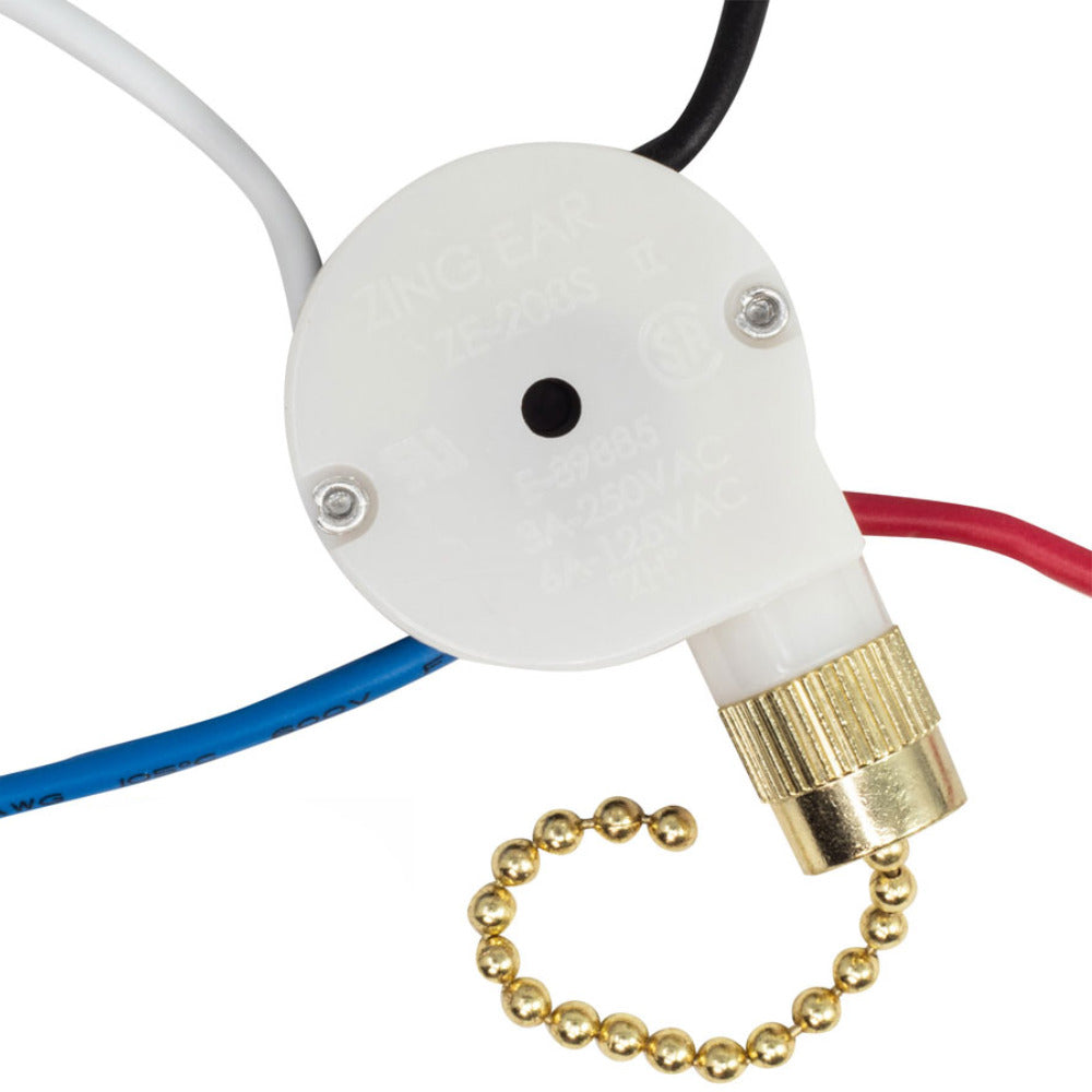
This wiring instructions page is for switch with four terminals as follows:
- Terminal number sequence is 1-2-3-L in counterclockwise direction
- The black wire (AC line/power) is attached to terminal "L"
- Internal positions: Off, L-1, L-2, L-3

If the old/existing switch does not have the same information as above, then this wiring instructions will not work.
Steps
- Turn off electrical current at source. Failure to disconnect power may cause electrical shock, fire hazard, serious injury, or death
- Do not cut the wires off the old switch. multi-strand wires are soldered together so they can be re-attached to the new switch
- Take a note of the color of each wire and the terminal number they are attached to
- Remove the wires from the old switch
- Make sure that the wire lead length is the same length as the line beside word STRIP. If the the lead length is shorter, stripe the wire to make it the same length
- Attach the wires to the new switch as noted in step 3. Wires should be inserted into the terminals on side of the switch not the holes on surface
Color Codes Guide (Your Fan Wires Color & Position May Vary)
- Wiring diagram for Harbor Breeze ceiling fan:
- 1=Gray, 2=Brown, 3=Purple, L=Black (AC line/power)
- Wiring diagram for Hunter ceiling fan:
- 1=Gray, 2=Brown, 3=Green, L=Black (AC line/power)
- Wiring diagram for Hampton Bay ceiling fan:
- 1=Purple, 2=Brown, 3=Gray, L=Black (AC line/power)
- 1=Red, 2=Purple, 3=Yellow, L=Black (AC line/power)
- 1=Gray, 2=Brown, 3=Purple, L=Black (AC line/power)
- Wiring diagram for Sears ceiling fan:
- 1=Purple, 2=Brown, 3=Gray, L=Black (AC line/power)
- Wiring diagram for Emerson ceiling fan:
- 1=Gray, 2=Yellow, 3=Purple, L=Black (AC line/power)
- Wiring diagram for Casablanca ceiling fan:
- 1=Green, 2=Blue, 3=Yellow, L=Black (AC line/power)
- Wiring diagram for iliving outdoor fan:
- 1=Blue, 2=White, 3=Red, L=(AC line/power)
- Wiring diagram for some other ceiling fans:
- 1=Purple, 2=Yellow, 3=Blue, L=Black (AC line/power)
- Wiring diagram for some basket fans:
- 1=Red, 2=Blue, 3=Black, L=Black (AC line/power)
Additional Wiring Guide (Your Fan Wires Position May Vary)
- 1: Attached to the reverse switch terminal
- 2: Attached to the motor wire
- 3: Attached to the motor wire
- L: Attached to Black wire (AC line/power)
Capacitor Information (Your Capacitor May Vary)
Usually, there is no connection between this switch and the fan capacitor. The fan capacitor should have one microfarad reading with 2-3 wires. Two of the wires should be the same color on one end, for example, one end has 1 white wire while the other end has 2 red wires.


2 comments
For the Record
L is line
L1 is LOW speed,
L2 is Med speed,
L3 is HIGH speed
Jake Jacobsen
As I understand things ( as I cannot find an answer here)
L is line
L1 is high speed,
L2 is Med speed,
L3 is low speed
Is this correct for the 208S 2
Thanks , Pretty sure this is correct but just want to check. Do not yet know what brand ceiling fan I am working on tomorrow so I cannot supply that information.